How to Select the Right Hall Effect Sensors
How to Select the Right Hall Effect Sensors
There are numerous sensors existing, but how to make the right choice for your application? That’s related to the sensor selection procedure. The selection of an appropriate sensor is based on matching the operating characteristics of sensors to the requirements of an application. Now let’s see the selection procedure of hall-effect transducers based on the 4 key technical parameters.
The Measured Current Value & the Current Type
The measured current is AC or DC signals?
Ø AC signal: Confirming the frequency of the measured current signal. If it is the high frequency signal above 10KHZ, the closed-loop hall effect sensors will be the options. If the measured current signal frequency is less than 10KHZ, both the closed-loop and open-loop hall effect sensors are workable.
Ø DC signal: Please move to the next step.
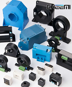
The Type of the Measured Current Busbar ( the Primary Test Lead)
Ø If the measured current busbar is cable, the hall-effect sensors with the round hole in the center will be selected.
Ø If the measured current busbar is copper bar, the hall-effect sensors with the square hole in the center will be selected.
Ø Hall effect sensors with PCB-mounting installation are also available for the measured object requiring PCB-mounting.
Please choose the suitable hole size of the hall sensors according to the size the measured objects. And make sure the measured busbar is as big as the hole of the hall sensor.
The Power Supply Mode: Single Power Supply & Dual Power Supply
The voltage of hall sensors with dual power supply:±12、±15V、±18 V,±24 V;
The voltage of hall sensors with single power supply:+3.3 V、+5 V,+12 V,+15V,+24V;
Install Caution:
1. Connection mode, connect according to the specification requirements. The wrong wiring may damage the sensor.
2. Full hole measurement, the accuracy is the best. If the measured current is lower, you can make more turns to increase the accuracy.
3. Hall sensors are the magnetic inductive products, which are easily interfered by the strong magnetic field. Please avoid to install the hall sensor to the places where the large power transformer or heavy current busbar are nearby. If unavoidable, please move the interference source of 2 times higher than the rated current of the sensors to the place where 5-10cm is far way from the hall sensors.
4. Sensor’s magnetic saturation point and circuit saturation point make it’s overload capacity strong. But there is time limit for the overload capacity: the current with more than two times shall not exceed 1 minute.